HERMS Ramping Experiments
While I was doing a 15 gallon turbid mash with 5 temperature steps, I
decided to do some research into performance of different
temperature control algorithms.
Common practise on a HERMS system is to control the mash
temperature indirectly by varying the temperature of a
direct-fired hot liquor tank. Wort flows out of the mashtun,
via a pump, and through a heat-exchanger coil in the hot liquor
tank and then returns to the mashtun. If you want your mash to
be 65℃, then setting your HLT to 65℃ is a reasonable
approach. In a world with no thermal losses, this model should work
well.
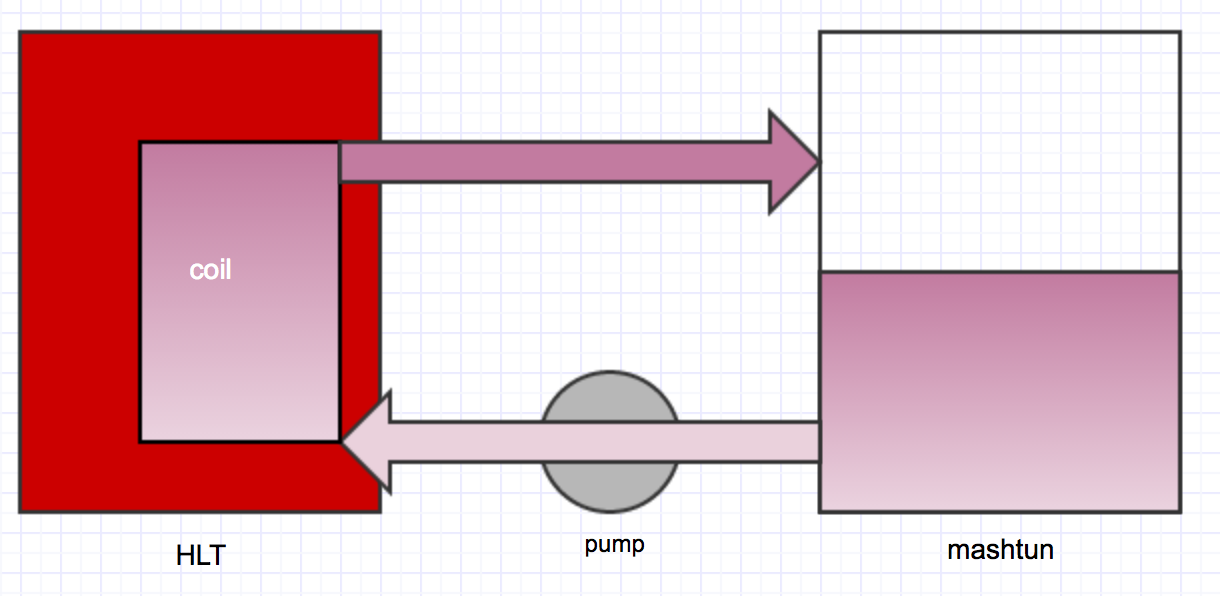
In reality, thermal losses from the HLT, hoses, and pumps leads
to a condition where there is a small differential between the
HLT and mashtun. My home brewhouse, which consists of an 80 litre
(20 gallon)
mashtun, a 60 litre (15 gallon) HLT fired by a 5500W electric element, and a 14m (45 foot) HERMS coil driven by a
pump that moves 10 litres of wort per minute through the coil
typically requires the HLT to be set around 1 - 1.5℃ hotter
than the mashtun when brewing 60L batches. This can vary
slightly based on the temperature setpoint, mass of grain,
volume of water in the mashtun, and volume of water in the HLT.
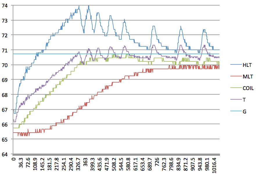
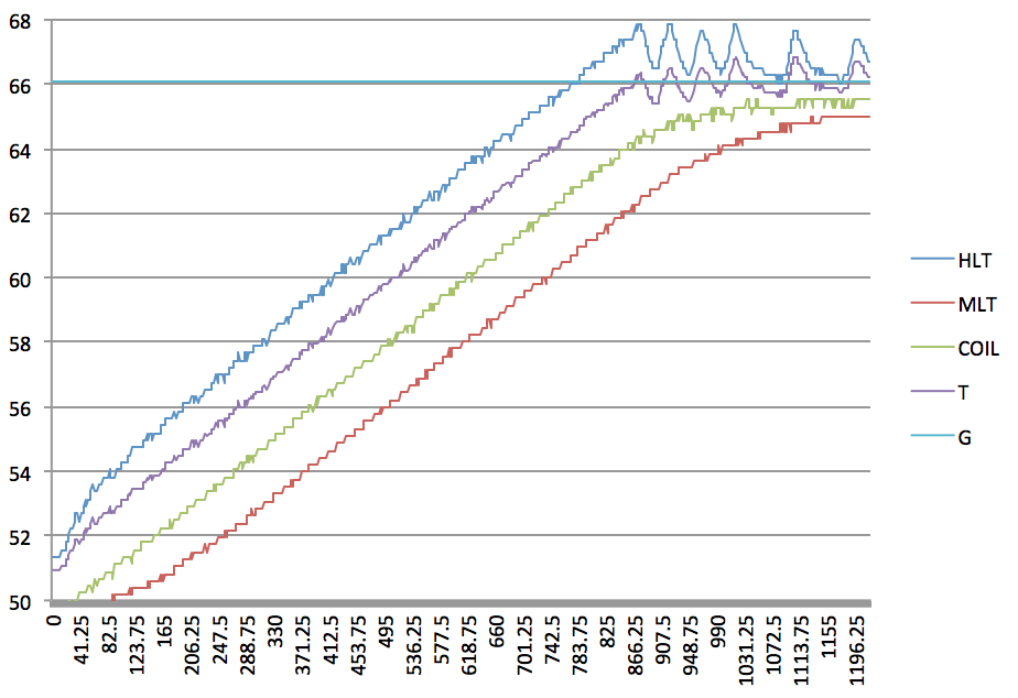
Here is a plot of my system's response when ramping the mashtun
from 50℃ to 65℃.
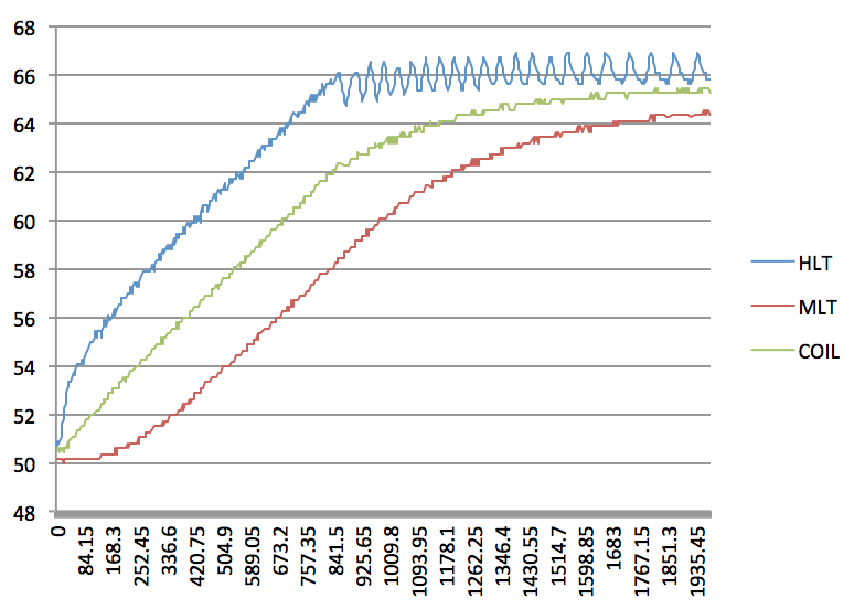
The blue curve represents the temperature in the HLT. The green
curve represents the temeprature of the wort at the exit point
from the heat exchanger coil where it returns to the top of the mashtun.
The red curve represents the temperature of the wort at the
bottom of the mashtun as it exits the vessel and heads towards
the pump. The thermal gradient in the HLT is minimized by a
recirculating pump which keeps the tank stirred and fairly
uniform. You can see here that my HLT setpoint is just over
66℃. There is a control deadband of about 0.5℃ around
the setpoint, which is why a zig-zag response can be seen.
Rate of Heat Transfer
If an equal mass of hot and cold water are mixed together, the
resulting final temperature of the combined system is a weighted
mid-point between the two initial temperatures. e.g., 10L at
20℃ and 10L at 30℃ yields 20L at 25℃. In a
heat-exchanger like a HERMS coil, the volumes don't actually mix,
but instead flow past each other at a specific rate for a specific
period of time. This results in a slight cooling of the water in
the HLT and a warming of the wort flowing through
the coil. The rate at which heat transfers across the stainless
steel wall of the heat exchanger coil is determined by
its thermal
conductivity and the difference in temperature on the inside
and outide. In a nutshell, the larger the difference in
temperature on either side of the wall, the quicker the transfer of
energy (heat). This is the same reason an ice cube melts faster in
hot water than in cool water. A final point to note here is that
the temperature of the wort leaving the heat exchanger will never
fully reach the same temperature as the water in the HLT, since the
system is trying to reach a point in between the temperature on the
inside and outside of the coil. The wort can get closer and closer
to the HLT temperature the longer it stays in the coil, but it will
only asymptotically approach the HLT temperature. You can see this
in the above graph -- when the HLT and wort temperatures are
further apart, the rate at which heat is transferred is faster
(steeper slope), but when the temperatures are closer together (at
the start and end of the ramp), the rate of change is slower
Purposely Overshooting
By allowing the temperature of the HLT to overshoot the target
mash temperature by a calculated amount, it is possible to
reduce the time required for the mash to reach it's final
temperature. This is because the temperature differential in the
heat exchanger is being increased, thus increasing the rate of
heat transfer.
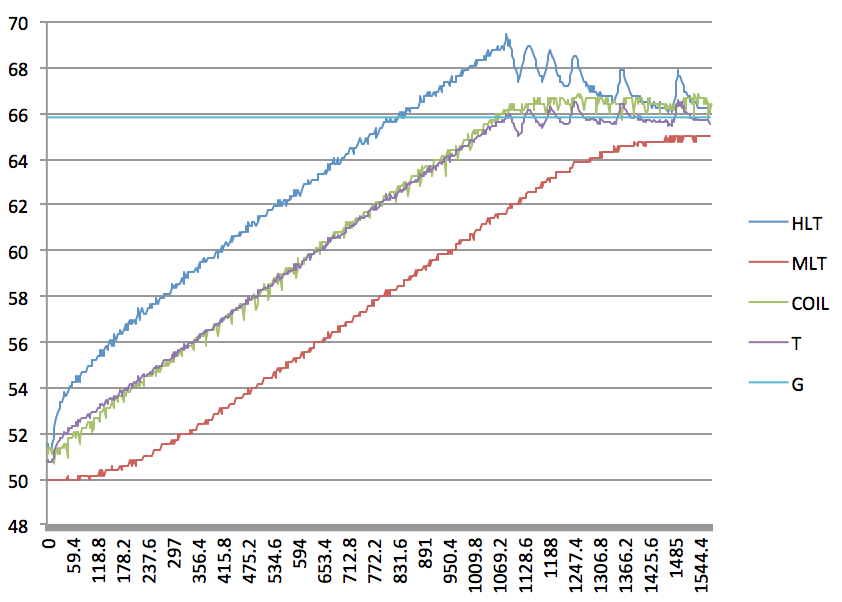
You'll note that 2 new curves are plotted here -- T and G. The T
curve indicates the overall system temperature, which is the
weighted sum of the thermal masses of both the HLT water and the
mash. G is the final weighted goal state for T.
The formula I am using to compute the current system temperature
(T) is:
T = kHLT × tHLT + kMLT ×
tMLT
where:
- kHLT is the proportion of mass in the HLT (e.g., 50 /
(40+50) = 0.556)
- kMLT is the proportion of mass in the mashtun (e.g., 40 /
(40+50) = 0.444)
- tHLT is the temperature of the water in
the HLT
- tMLT is the temperature of the mash in
the mashtun
And the goal (G) is defined as my desired final steady-state
arrangement where tMLT = 65℃, and
tHLT = 65℃ + tOFFSET,
with tOFFSET being the known offset that I need
to maintain my HLT at in order to hold a given mash temeprature
(approximately 1.5℃ in this case). This yields a goal
state of:
G = 0.556 * (65 + 1.5) + 0.444 * 65 =
65.834℃
When the system temperature reaches this point, I know that there is an equivalent
amount of heat in the system to reach my goal condition where
the mash temperature is at my desired setpoint and the HLT is
a bit warmer to maintain that mash temperature. The heat may
not yet be evenly distributed, but in a closed system with no
losses, the heat exchanger would take care of that. This is the
important bit...
The two vessels are considered to be a single
system, and energy is only added to the system when the overall
temperature is below the goal.
You can see that the HLT reaches 66℃ at about the same time
as in the previous case, but instead of cutting the power
at that point, the HLT is allowed to continue heating up until
the overall system temperature (T) reaches the goal (G). Again, the
reasoning here is that the heat-exchanger will finish the work of
moving the excess energy from the HLT to the mash. As a result of this HLT overshoot,
the temperature difference between HLT and mash is allowed to
remain larger for a longer period of time, thereby increasing the
rate at which energy is transferred to the wort. Additionally, without
any further energy input, the overall system temperature (T)
cannot increase any further, which ensures the mash doesn't
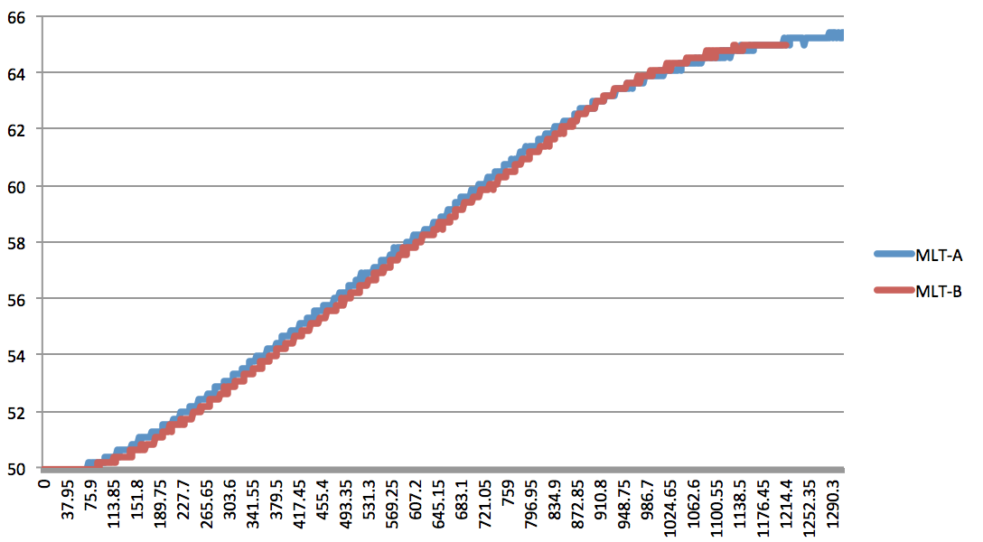
overshoot. When the 2
graphs are co-plotted, you can see that there is a time savings
of around 25%, or over 8.5 minutes:
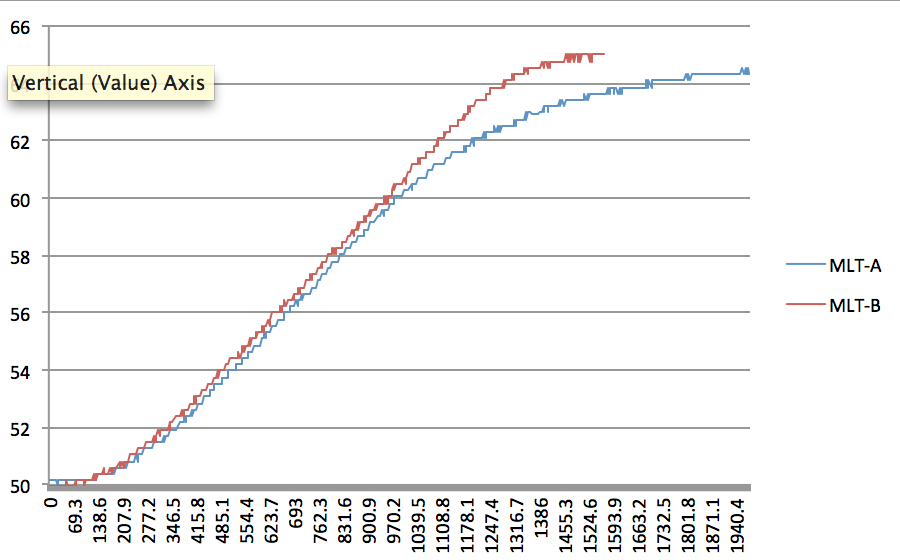
You can see the simple control algorithm's impact on the
mashtun temperature as the blue MLT-A curve, and the overshoot
algorithm's impact as the red MLT-B curve.
As a note, my turbid mash schedule required a dough-in at 45℃ and
rests at 50℃, 65℃, 70℃, and a mash-out to
76℃. In the end, for this 15 gallon batch, I saved almost 30 minutes by using this
overshooting control algorithm.
Overheating the Mash?
Is it possible that the over-heated HLT could lead to
de-naturing of the enzymes in the wort? If you are ramping
temperature for dough-in or mash-out, this shouldn't be a
concern, however if you are doing temperature ramps for alpha-
or beta-amylase rests, then it might be. Let's take a quick
look at a section of one of my temperature plots for a 65℃
- 70℃ ramp.
You can see that the green curve does exceed the mash setpoint
of 70℃, but
recall that the green curve in my system is always slightly
higher than the mash temperature, due to the nature of the
losses in the system. The difference in temperature from my
setpoint appears to only be around 0.5 - 0.7℃ in this
case. While that may be enough to impart an accelerated
denaturing, keep in mind that the wort will only reach this peak
temperature just as it is finishing it's run through the HERMS
coil. If the wort is only overheated for a brief moment before
rejoining the full volume of the mashtun and equalizing, then
the denaturing effect is greatly reduced.
- My pump moves 10 litres per minute through the coil.
- The volume of my HERM coil is approximately 1.75
litres.
- 1.75 litres will be moved through the coil in 10
seconds.
- The temperature gradient through the coil is at most around 4℃
in the above plot (inflow to outflow).
- This means that only around 15-20% of the wort in the coil
will be above 70℃ at any given time.
- 20% of 10 seconds is 2 seconds, so the wort is only
overheated slightly for 2 seconds.
- It takes 240 seconds to completely cycle the 40 litres of
wort through the HERMS coil.
- The wort only spends 0.8% of it's time above the 70℃ setpoint.
Now I don't know specifically how long it takes to denature the
enzymes, but if the wort is only overheated at a duty cycle of
less than 1% (14 seconds over a 30 minute step) and only by an amount on the order of half a
degree, then I am not overly concerned. Also, keep in mind that
this overshoot only exists for a small duration of time during
the temperature ramp, after which point, steady state is
resumed (although I always have a slightly higher HLT setpoint
than my mash). Frankly, I would have
more concern if I were operating a RIMS system which applies a
much greater localized heat differential to the wort, or moreso
during a typical single-infusion mash where the full quantity of grist is purposely immersed in
over-heated strike water.
Comparisons at 40kg
Here are a series of comparative plots for my 40kg setup ramping
between different temperature points and a note on how much time
was saved using the overshoot algorithm. The 40kg figure comes
from the specific grain bill I was using for my last brew which
was approximately 34kg of water plus 13kg of grain (34 + 0.45 ×
13 = 39.85kg equivalent thermal mass). My HLT was filled with
50kg of water.
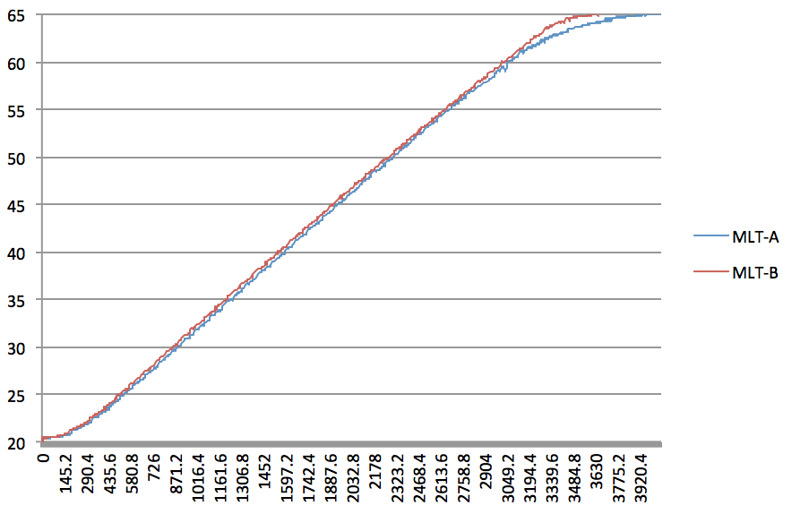
Ramp from 20℃ to 65℃ (strike). 362 seconds saved
(10%). Probably the most underwhelming, percentage-wise, but in
absolute terms, that's still 6 minutes.
Ramp from 50℃ to 65℃ (protein to beta). 517 seconds
saved (26%).
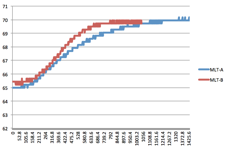
Ramp from 65℃ to 70℃ (beta to alpha). 330 seconds saved
(30%). Over 5 minutes in a 5 degree ramp.
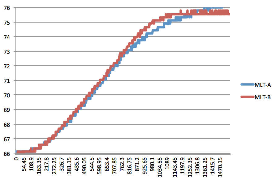
Ramp from 66℃ to 76℃ (mash-out). 170 seconds saved
(13%). For mash-out, we can typically do better, since the final
temperature isn't really that important. If you are going to keep
heating your HLT for lautering (e.g., 90℃), then you can save
even more time here by just letting it keep firing, pulling the
mash up faster.
Variables
After some discussion with members of my local club, some
concerns were raised that the performance of my system is
different from that of others. Specifically, the temperature of
my mashtun was lagging by several degrees when ramping, wheras
others reported only 1-2 degrees. It's true. Different behaviours
will be seen when system variables are adjusted:
- Decreasing the mass in the mashtun reduces the thermal lag
during ramp since the volume cycles quicker through the heat exchanger,
and the ratio of returning wort at warmer temperature to
cooler wort in the mashtun is larger.
- Increasing the mass in the HLT reduces the thermal lag
during ramp since the HLT has more thermal mass and does not
cool off as quickly overall due to it's larger volume.
- Increasing the ratio of water in the HLT to the water in
the mashtun will reduce the thermal lag due to the combination
of the two above points. e.g., with 1000L in the HLT, and 1L
in the mashtun, there will be almost no lag between the
vessels (excluding the usual losses).
- Increasing the efficiency of the heat exchanger will lead
to lower lag times (e.g., longer coil, better conductivity,
higher flow rate)
- Reducing thermal losses in the mashtun circuit can reduce lag time
(e.g., insulating), and reducing thermal losses in the HLT
will lead to quicker ramps.
It's quite likely that people who are not experiencing as much lag
time between HLT and mashtun as me are also brewing smaller batches,
and/or possibly with more water in their HLT. I re-ran all of my
temperature ramps using a smaller 20kg mashtun load, and the
results between the two algorithms were quite comparable:
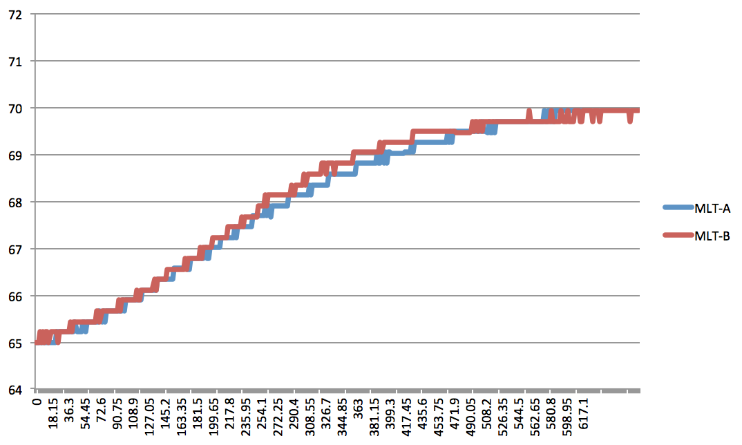
The reason that there is not much difference is that the
overshoot algorithm exploits the fact that the HLT reaches it's
target well in advance of the mashtun due to the temperature
lag. If the lag is small, then the HLT still reaches it's
target well in advance, but the overall system temperature (T)
is much closer to the goal (G) due to the much higher weighting
of the HLT component of the system temperature (T). As a
result, the overshoot for the HLT is not allowed to be as large
as in the 40kg case.
You can see here that in this 20kg ramp from 50℃ to
65℃, that the HLT never gets hotter than 68℃ whereas
in the 40kg plot, the HLT temperature
goes as high as 69.2℃. Additionally, you can see that
the lag in the 20kg plot tops out around 5.5℃, whereas it is as
high as 8℃ in the 40kg plot. I
should also draw attention to the sawtooth pattern caused by the
0.3℃ system temperature deadband around G. This could
probably be reduced.
Other Considerations
Some other musings gathered during the investigation:
- The temperature of the HLT should not be allowed to
exceed 100℃ for obvious reasons.
- The delta between the mashtun temperature and the MLT
temperature should not be allowed to be high enough that
denaturing could become a serious concern. (Practically, it
is probably quite challenging to achieve denaturing unless the
flow rate is very slow).
- Knowing the thermal masses of the hot liquor and mash is necessary
in order to properly calculate T and G. Any brewer should
already have these figures handy.
- Knowing the thermal losses of the system, further
improvements could be made to keep the HLT temperature higher
for longer, rather than resorting to the inevitable duty
cycling towards the end of the ramp. This would require some
predictive modeling, but should not otherwise be
difficult.
- The system losses can easily be measured at any time by
knowing what the input power is (e.g., 5500W)
- Accurate ETAs could be computed.
- Rather than my crude deadband element control, I should look
towards more fine grained power control which controls duty
cycling based on a PID algorithm, but on the timescales we
operate at, the benefit may be trivial.
- The overshoot algorithm also does a better job at reacting
to transient events, such as topping up the HLT with cold
water, ramping temperature down, etc. This is because it is
always operating with knowledge of the full system
temperature.
- If pump controls are available to the control algorithm,
then the HLT could be further over-ramped, at the expense of
having to shut down the mash pump once the setpoint is
reached. This could also act as a failsafe against thermal
runaway due to an inadvertently shut-down HLT pump or a stuck
element relay, etc.
- If cold liquor is available, then the HLT could similarly
be further over-ramped, and then rapidly cooled back to the
goal condition. The HERMS coil connected to household water
at 10-15℃ can very rapidly cool the HLT.
Conclusions
In certain system configurations, it can be beneficial to
purposely over-ramp the HLT in a HERMS brewing setup to reach
different temperature steps if:
- The thermal lag between the HLT and mashtun is high
- The ratio of mass in the HLT to the mass in the mashtun is
low
There are possibly other situations which would warrant it, such
as low pump flow rate, or high system thermal losses, but these
should also manifest as high lag time.
I am considering leveraging the knowledge gained from this
experiment over to the STC1000+ project for use
in fermentation chamber temperature control.