| Sean McVeigh's MAME
Cabinet Project see MAMEWorld to figure out what on earth I'm talking about |
|
| Introduction Design Cabinet Controls Interfacing PC Guts Audio Video Links |
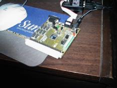
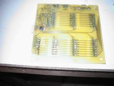
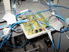
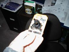
Interfacing (photos forthcoming) Now, it's really cool to have a full sized arcade machine in your basement, but it's not very useful unless it can play games. I needed to interface the controls to the PC in some way. I had read about products like the I-Pac and J-Pac from Ultimarc but I really didn't want to pay for a product that I knew I would have more fun designing myself. Digital Controls The digital controls comprise the joysticks, pushbuttons, and coin doors. I happened to have a Cygnal C8051F020 microcontroller development board lying around the house, so I figured I'd have a go with it. This family of microcontrollers is packed full of nifty features, like 500ksps ADCs, DACs, temperature sensors, PWM generators, SPI, I2C, UART controllers, etc. I actually used a 14-pin DIP prototyping C8051F300P micro for the temperature controller in my wine cellar, complete with logging to an external system, etc. But enough technical jargon...the bottom line is that although I could buy a C8051F310 for $11, I'm going to try and order a sample from our rep in Ottawa (we are using these microcontrollers in products at work, hence the reason I have a development kit in the first place). While I am prototyping on the '020, I doubt if I can fab a PCB at home with a fine enough pitch to mate with an TQFP-64 or TQFP-100 package, hence my decision to go with the '310 which is available in an LQFP-32 package. The only downside of this is that I only have about 28 pins of I/O on this chip. How to proceed when I have approximately 50+ inputs, and I need at least 4 pins to do the keyboard interface I had planned.  One of the guys at work offered a really clever idea to get around this problem. If the microcontroller has an ADC on it, it would be possible to build a manual DAC of sorts by hooking resistors between controls creating a voltage dividing ladder. I was leaning towards building a standard 8x8 or 4x16 matrix switch using diodes and running a pair of wires to each control switch. My solution would require at least 16 pins and 64 diodes, not to mention something on the order of 128 individual wires (72 if I shared the common scan lines). I was planning on using cat-5 or cat-3 as my wiring bundles, so it would still be manageable, although I would eat up much more board space trying to place all of the required screw-down headers. Eric's solution would require something on the order of 16 analog inputs and a ground wire. ie. 17 wires leaving the PCB to connect to groups of controls. Much more compact, and using approximately the same pin-count on the microcontroller as my solution. I originally discounted this idea because I was planning on using the C8051F020 kit that I had at home, which only supports 8 analog inputs (and running an 8-bit DAC into a 10 or 12-bit ADC worried me). Since I now planned on using the '310 microcontroller (as the LQFP-32 package is workable in a home-etched PCB with 10 or 12-mil traces) which supports somewhere on the order of 24 analog inputs, Eric's solution was again fair game. One other problem is that the '310 only has 1 ADC into which you multiplex several analog inputs. This means I need to scan the input groups in a round-robin fashion. I would have had to do this with a matrix switch anyways. The only difference is that the ADC mux has a certain amount of required settling time when switching inputs, so I have to take that into account when determining my scanning rate. The ADC can be run at 200,000 samples per second, and the settling time requirements are quoted at about 3 SAR clock periods for typical applications. The SAR clock can be run at up to 3MHz, so 3 SAR clock periods adds up to about 1/5th of one ADC sample period. Even if the settling requirements were 10 ADC samples, I'd still be able to sample at a rate of 20KHz, and if I round-robin the 16 inputs at 20KHz, that yields still over 1KHz sampling rate overall. I don't know of many people capable of mashing buttons at a rate of 1000 times per second, nor do I believe the keyboard interface would support such a rate. In the end, I will probably be able to sample the entire panel 10,000 times per second, with a modest settling time allowance and perform some debouncing in software to suppress glitches should they arise. Update: I can't seem to build DACs with enough reliability to do the DAC/ADC route (at least not with the components I have on hand). Since I already have all of the diodes to build a matrix switch, I'm just going to go ahead and do it the digital way. Enough about pin-count resources.. How on earth was I going to get the information into the PC? Well, since MAME primarily supports keyboard input, coding up a keyboard interface on the Cygnal microcontroller seemes the logical route to take. Little did I realize the fun I was in for. Now, I already knew that keyboards use a serial interface to talk to a controller on the PC-side of things. What I didn't know was that the protocol used wasn't a standard UART-type asynchronous protocol, and so I couldn't just use the UARTs in the microcontroller to do the interface. A bit of researching later, and I found that the PS/2 keyboard (and mouse) protocol uses a synchronous 2-wire 5-volt serial link. Piece of cake, especially since it turns out that the keyboard gets to drive the clock signal. Well, it took about one night to code up a state machine to drive the keyboard protocol. When I hooked it up to another PC in the house, it worked first time (actually second time, I had my 2 pins reversed on the first try). The next test was to see if the microcontroller would be detected as a keyboard when I rebooted the PC (since a lot of PCs will not boot without a keyboard). Needless to say it did not work. I decided that I would need to scope out the signals and find out what I was doing wrong, so I booked some equipment out in the lab at work for the weekend and set up camp. 3 hours passed and I determined that I had a problem with what clock edge I was sampling the data line on in the ingress direction, which explained why the commands sent from the PC never quite made sense. After fixing this, it still didn't work. I probed a real keyboard at this point, and I could see no visible difference from the waveforms I was generating. A few more hours of pondering, and I figured I had a problem with my logic levels. The data on the scope read one thing, but my debug output from the microcontroller indicated it was reading something else. Shortly thereafter, I started to examine the analog levels on the scope. It turns out my 0-level was bang on at 0V when I was driving the bus, but when the PC was driving, it was closer to 0.5V (and sometimes higher). This was a bit perplexing since the data line is an open-drain shared bus with a pullup on it. It seemed the PC wasn't able to overdrive the pullup on this line. Perhaps it was expected to be driven into a somewhat higher load at the keyboard side, I'm not sure. A pull-down resistor of about 20K on the microcontroller side of things solved the problem with complete reliability, and at the same time brought the 5V logic high level down to a more familiar 3V (the microcontroller has 5V tolerant inputs, but why push your luck). Now I hooked the ad-hoc controller that I had constructed as a proof-of-concept prototype directly up to the microcontroller. I used one pin per control point at this time, because I only had 10 inputs to scan and 62 unused pins. After cabling the rig up to the keyboard port on my PC, I launched mame and ran a shoot-em-up game to test with. After completely dominating the right-hand side of the screen, I determined that I had a problem with my scan-code mappings on the microcontroller (I was never releasing the right-arrow key). After fixing this small bug, the controls worked flawlessly. I demoed it for some guys at work and got positive reviews. Now all that remains is to lay out the 8x8 matrix switch and microcontroller on a simple 6x6" single sided PCB. I don't look forward to all of the drilling that will be required to mount 64 diodes. I'll update this page when I have the board ready to go. Update: I've got the board complete, everything mounted and it works flawlessly. One of the switches on the player 4 joystick is probably oxidized when in the closed position, so I've reversed the polarity of the switch in software and rewired it to use the N/O contact, problem solved (although Craig from X-Gaming said he'd send me some replacement switches, as there is a 1 year parts warranty). Here are a couple of shots of the finished board.  You can see the microcontroller on the left. It is only 9mm square and I had to go down to 12-mil traces to connect it. (it's approximately 1 pin per 0.8 mm). Incredibly, I got it soldered down on the first try with no glitches. I did have a shot of the other side of the board, but it suffered from thumb-in-the-shot-itis, so you'll have to settle for this shot of the board with all the wiring hooked up.  I've even got a spare PS/2 port on there in case I ever decide to add a passthru feature. The DB-9 connector is there primarily to provide debugging output from my firmware code. I haven't actually put the RS-232 level converter on the board, so it is currently inactive. I managed to do all of my debugging before I moved to this board though, so it's no problem. In the future, perhaps I'll write a bootloader and have firmware downloading through this port. You can see my 10-pin JTAG header on the left-side of the board. I installed the programming tools on the MAME PC, so I can update firmware from in-cabinet. No need, or desire, to disconnect the PCB and haul it upstairs (I actually did haul the entire panel upstairs once already, and I decided I don't want to have to do that again). Analog Controls The analog controls comprise the trackballs and spinner. Again, I read about some product from Ultimarc and figured I could do the same on my own. Since MAME supports mouse input (and input from 2 mice in some versions), all that needed to be done was to implement the mouse protocol in the Cygnal microcontroller. Hold on a second. Why go to that extra effort when I have a bunch of old mice scattered about the house. After disassembling one of them, I was presented with the following scene.  There are 3 nice small microswitches in the 3-button mice I've disassembled which I quickly removed to be put to use in some future unspeakable project. A mouse works on a fairly simple principle: 2 perpendicular wheels rotate when the mouse ball is rolled, giving the distance travelled in both X and Y axes. Each wheel has a series of evenly spaced slits cut into it. A pair of infrared transmitters produces 2 beams which intersect the slits in the wheel. A pair of infrared receivers located on the other side of the wheel receives the beams from the transmitters. As the wheel rotates, the beams either pass through the slits or are blocked by the wheel and are detected by the receivers. The receivers are placed in such a way as to be approximately 90 degrees out of phase from each other. This means that just as one beam is being blocked out, the other beam is still being passed. The order in which the beams are blocked out indicates the direction of the wheel rotation. In simpler terms, one beam can be used as a clock signal to sample the other on transitions. The number of times a receiver is pulsed indicates the number of slits that have passed in front of the transmitters (actually, in all of the mice I have disassembled, only one IR LED is used per pair of receivers). This circuit is duplicated for the other axis. On to the trackball. I have seen a softcopy of the datasheets for these trackballs online, but at the time of writing, I cannot locate them. The trackballs are made by Danaher Controls, and are of the type you would use in industrial applications. Each trackball has a modular RJ-45 jack and the hard-copy of the datasheets that I received when I bought them indicate that there are 6 pins of interest: power, ground, XA, XB, YA, YB. The diagram of the XA/XB and YA/YB waveforms looked strikingly like the sort of signals that you would expect to see produced by the optical encoder systems of a mouse. My plan was then to simply remove all of the optical components from the mouse PCB and wire in the outputs from the trackballs encoders. The trackballs are rated at 200mA max operating current at 5V, and I know that the PS/2 mouse port provides 5V. I recalled reading somewhere that keyboards are expected to draw no more than 300mA at 5V, so I presumed that the mouse port probably shared the same fuse as the keyboard port. After browsing some motherboard specs, I determined to just give it a try (your mileage may vary here, I wouldn't recommend drawing 200mA from your mouse port unless you are certain of your motherboard power specifications) as it was indicated that most mouse/keyboard ports have about a 1A fuse on them. Well, would you believe that everything worked on the first try with the trackball-mouse hack. No need to look any further. In the final design, I will be drawing 5V directly from a PC power supply, so no need to fuss over loading the mouse or keyboard ports. In fact, if I don't need to draw power from these ports, I can instead monitor their power lines to determine when the PC is being powered on or off and reset my controller accordingly. All that remains for the analog controls is to figure out how to hook up the spinner, when I get around to completing it. A spinner is just one axis of a trackball or mouse, in that it has only one slitted wheel that spins past a pair of IR receivers. It should be trivial to fabricate such a wheel and mount it to a shaft and knob and have it spin past a pair of optical junctions. I can probably reuse the removed mouse optics for this purpose. I have decided that the construction of the encoder wheel will amount to mounting an acetate transparency to some sturdy transparent plate that gets threaded onto the shaft of the spinner. The transparency will consist of a set of opaque areas evenly spaced around the circumference where the IR beams will be broken as the artwork spins past. Since I am fairly certain that I can only support 2 mice, I have opted to sacrifice one axis of one of the trackballs to interface with the spinner. I was planning on coming up with a fancy system where the microcontroller would decide which control a player is using, and switch off the unused one accordingly, but cabinet shake could probably cause it to glitch. The next idea was to use a DPDT relay to switch between the busses of the mice where they are fed into the PC. A third idea was to use a DPDT relay to switch between the analog waveforms which are fed into the mouse encoder on the mouse PCB, allowing me to select to either use the X axis of the trackball or the spinner. This idea seemed the most reasonable. After determining that I'd need an external switch to select controls anyways, I decided to cut the relay out of the picture entirely and just use an old-fashioned mechanical DPDT toggle switch. I've asked my brother-in-law to machine me an aluminum spinner knob, as I couldn't find anything like what I wanted at Home Depot. The closest I could find was cabinet hardware, and I didn't think that would quite fit in with the look and feel of the system. Once I have the knob, I can build the spinner assembly and test the mechanicals, adjusting the flywheel weighting, etc. The electronics for the spinner will be assembled last. I could just go out and buy a spinner from someone on eBay, but I am morally opposed to giving someone something on the order of $40USD + shipping for such a thing when I know it should cost about $10. Update: So the knob that Phil machined for me was very nice, but the bore wasn't wide enough to fit the shaft, and he must not have had large enough stock to machine this from, as it turns out to be only about 1-1/4" outer diameter (perhaps a bit cramping if playing for extended periods). After weighing the cost of building the support bracket and miscellaneous hardware vs. a bargain spinner I saw on ebay for $10, I opted to grab the spinner off eBay. I got it for $13 in the end which is acceptable. It's the model from the old star trek game, so probably not as popular as the spinners from tron or arkanoid (which fetch higher premiums usually). Of course, a spinner is a spinner is a spinner when you are doing it all yourself, so this should do quite nicely. ...more... |